Shooting, Developing, and Scanning 16mm Film
For my Fall 2015 semester, one of the projects I set myself on undertaking was trying to figure out how to shoot a movie on film without spending a lot of money. I would find a camera, get some old film, develop it somehow, and digitize it with some sort of scanning machine. Developing and scanning can be done by people who know what they're doing in exchange for money, but that's not what this is about. This is about taking something I've got no clue on, and making something real. This is a super fun project.
Camera
After some research, I decided I wanted to shoot on 16mm. Other possible formats include Super 8mm and 35mm. Super 8 was a home movie standard, and 35mm was and still is a feature film standard. 16mm is a median in quality, price, and ease of use. It's popular in film programs in schools.
As for the camera, I eventually narrowed it down to either some Bolex H16 model, or the Krasnogorsk-3. Bolex H16s are iconic, and different models have been produced starting as far back as the 1930s. The Krasnogorsk-3 is a Soviet camera built from the 1970s to early 1990s. For $100, I decided to go with a Krasnogorsk off of eBay. It's a solid camera, and I already had a few lenses that match the mount (m42).
Film
Initially, I got a roll of Kodachrome 25 film and shot a full 100' roll of test film with the intention of getting a good test reel.
It turns out that I didn't actually have the chemicals to develop Kodachrome. In fact, almost nobody does anymore. There are only a few (like 3) places that will still develop it. The film was supposed to be a test film that would be inconsequential if anything bad happened to it, but I actually liked what I had shot, so I sent it off to be developed in Georgia for $50.
Instead, I got a 400' roll of Ektachrome, which I was sure I can develop with the chemicals I have. It expired in 2002, but is still plenty sufficient for my needs. This was $25 on eBay. My camera can only shoot on 100' reels, so I had to manually wind film from this reel onto a 100' reel in complete darkness. I used my apartment bathroom with gaff tape sealing the edges and a towel sealing the bottom crack. This worked well.
Developing
This time the film I shot was actually inconsequential. I just shot people walking to class one morning on the way back from one my my classes. Nothing interesting at all. So if I mess up my first developing attempt, no big deal.
In order to develop the film properly, the film needs to be wound onto a special reel that spaces out the film evenly and allows chemicals to flow between the film with consistency. But this project is going to be cheap, so I'm not going to do it properly. I used a bucket, which is not an unpopular choice for this kind of rudimentary development process.
Mine is a 2 gallon bucket. Something like 1.5 gallons might have been more ideal. It's a bit large, so it takes more mixing to get the chemicals around. It has an assembly of PVC fittings sealed on the top which is designed to allow chemicals to enter and exit the bucket while disallowing light through. The inside of the pipe is painted black to block reflections. I also painted the bucket black to keep light from seeping through. The undeveloped film is loaded(stuffed) into this tank in a completely dark room, and then the chemical process can begin in a lit environment with the film safely inside the tank.
The process involves three basic steps: prewash, developer, and fixer. This part is sort of witchcraft. The chemicals I got all come in the form of white powder, which is mixed with warm water to make the solution.
The developer step is especially time sensitive. One of the flaws of my tank is that there is no air escape, so it takes a full minute to pour everything down the pipe and for everything to drain out. This makes timing much more difficult, since I have those gray windows when I'm pouring in and out. I'll have to add an air escape as a straw through the pipe or as a separate tube entirely.
Even though I shot on color film, the cheap process I use only produces a black and white image. I paid around $30 for a set of chemicals that will run a handful of batches.
Here's my first attempt:
I was super excited to actually get an image off the film, and that most of the shots had pretty decent contrast.
Scanning
My design is inspired by Kinograph, an open source film digitization project. Instructions on how to build the machine can be found on Instructables. The project aims to make film preservation accessible and not cost prohibitive.
Kinograph's parts cost comes in at $1,200. Although that's cheap compared to conventional film digitization options, that's expensive to me. Way more expensive than such a task seems like it should be. I cut the design back, and my final parts cost was less than $95, plus cost of camera, light source, and 3D printing. My results are easily comparable.
Here's what Kinograph looks like:
For what it is, Kinograph is extremely solid and a feasible solution for many looking to seriously digitize a larger collection of film. But $1,200 is far stretch from a no-budget DIY solution that I'm interested in. I have some immediate concerns for the design of the project, starting right at the parts list.
($212.19) Kinograph is built on a T-Slot aluminum frame. This is super solid, will hold up over time, and looks really nice, but not necessary. Wood or MDF is is cheap and plenty sufficiently sturdy for my needs. This thing isn't going to space, and it's not getting wild loading.
($156) Sheet acrylic and the panel holders to mount them to the T-Slot frame also looks nice, but again not necessary.
($125) High performance shaft couplings to join motor shafts and reel platters. My design would need to be beefed up in the reel platter department in order to accommodate full sized 35mm reels, but this still seems like overkill if this is going to be more of a DIY project. I won't make any definite claims because my needs in this area were less demanding (tiny 100' 16mm reels), but I'll just leave this here.
($33.99) I spend $7 on a functionally identical Arduino copy. Support Arduino if you've got the cash, but you don't have to when on a budget.
($19.99) LED diffusion sheet. Just use paper! $20 is mad.
($169.85) Power supply and two gearmotors. Again, I didn't build mine to spin a massive 35mm feature-length film, so a fair comparison can't quite be made. Also, this is where my design is completely different, which I'll discuss in a moment.
The cost of the project also includes a dedicated T-Slot camera mount that fixes the camera rigidly to the machine. This is unnecessary for me when I'm not going to be using this constantly and I can just use a the tripod I already have.
Kinograph works by having a gear motor spin a takeup reel, pulling film off the starting reel, through an arrangement of rollers that passes it through the scanning area, and finally winding the film onto the takeup reel. A camera captures images of each frame as it passes through the scanning area between the rollers.
One of the rollers that the film passes along is sprocketed. It has teeth built in that engage with the perforations in whichever size of film is being scanned (Kinograph can accommodate 35mm, 16mm, and 8mm formats). This engagement spins the roller predictably for any given length of film that passes by it. The roller also has wedges on its edges, arranged such that for each frame of film that passes, so does one wedge. These wedges engage with a rocker switch that, when pushed, would fire the camera shutter to capture an image of the current frame. This mechanism ensures that exactly one image is captured for each frame.
My first reaction to this design was, how could you ever expect spinning wedges on a rocker switch to give consistent results? Won't the frame jump around in position? In fact this does happen, as you can see at 1:06 in one of the project's videos:
Why not actually drive the film by its perforations some predictable amount, as a projector does, instead of pulling it at an unpredictable rate and letting the image capture follow? Certainly, this way would produce more stable results. This was the motivation for the difference in my design.
As it turns out, this problem doesn't actually really matter. It's easy to stabilize the images digitally, making any non-drastic inconsistency in frame position a nonproblem. Nonetheless, this was the issue I decided to pursue. I wanted to see if I could get my images totally solid in-camera by driving the film by the perforations rather than by the take-up reel. As of now, my images are about on par with Kinograph in raw capture stabilization.
Here's my design.
I used a modified version of Kinograph's rollers for this project. I sunk in larger recessions in the standard rollers to accept 608z bearings, which I had a bunch of. The originally intended bearings are probably better for this application.
For the sprocketed roller, I added a timing pulley on the top so the roller can be driven by a timing belt. This is the major distinction in my design. Instead of the film driving the sprocketed roller, the sprocketed roller drives the film. I used a stepper motor, which can be driven to reach desired positions precisely, given that the load is not overwhelming. I know exactly how much I need to spin the stepper motor to advance exactly one frame (thanks math), so in theory I should be able to advance the film exactly as much as I need to between each frame capture without the need to sense it.
Also note that there is a fifth roller in this design (lower right). This is to maximize engagement with the sprocketed roller. If the film went directly from the sprocketed roller to the take-up real, there would only be about 90 degrees of engagement. The fifth roller pulls the film all the way down around the sprocket to nearly 180 degrees of engagement.
This idea of the spinning sprocket roller doesn't work on its own. With just that pulley spinning, film may get pulled off the reel, but there's nothing motivating it to get back onto the take-up reel. For this problem, I had my motor pull double duty.
My stepper motor has a shaft that extends from both ends of the motor. The top shaft has the timing pulley that engages with a timing belt for the drive sprocket, and the bottom has another smooth pulley. This smooth pulley will engage with a belt (simple rubber band probably) which will spin the take-up reel, pulling the film off of the sprocketed pulley and onto the reel.
This pulley is smooth because the rate that the take-up reel has to spin for a given rate the sprocket is advancing film is not constant. Initially, the radius of the surface that the film is winding onto on the takeup reel is small, but as film stacks up that radius will increase. A larger radius means the reel will have to rotate slower in order to take up the same amount of film. A simple solution to this problem is to simply not rigidly engage the reel with the motor. Allow the belt to slip, and when the reel needs to move slower, it will just slip on the belt a tiny bit more.
Here's the build.
I was skeptical that those tiny grooves would actually be able to grab the perforations enough to advance the film, but it worked incredibly well on the first run. Way better than I thought it should have.
It turns out that as long as there is sufficient tension on both sides of the sprocketed roller, it works great. On the incoming side, that tension is maintained by felt clamps on in the scanning area. This may be damaging to old film, but I don't know. If it is, another option is to create tension by putting a constant torque on the starting reel. Tension on the outgoing side is maintained by a torque in the take-up reel, which is generated by the tension in the rubber band underneath that drives it.
Here's the result of the first test scan:
You can see there's this odd periodic oscillation, which actually occurs with a frequency that is a factor of the number of frames per revolution of the sprocket wheel. I think it was two revolutions per oscillation. There ended up being one or two particular teeth that the perforation would miss for whatever reason, causing the film to slide up a little each frame, before eventually snapping back into the correct position.
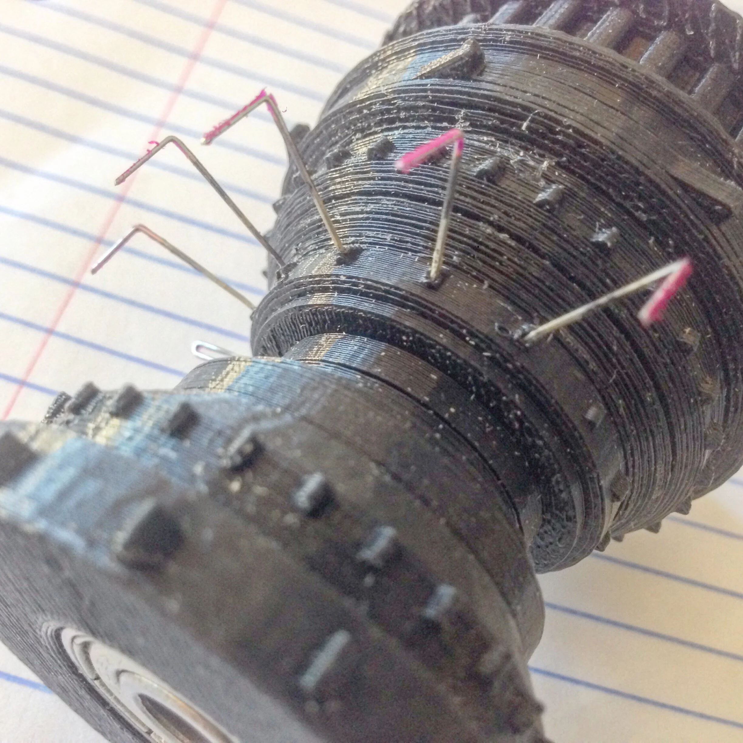
To fix this, I initially tried sanding down tiny bits of material off of problem teeth, and eventually I tried spiking the teeth with staples. This helped a lot with grip on the film, but it was impossible to place the spikes perfectly consistently, which caused similar problems.
I revised the design, making the nubs a little longer, and I also tried running the print at a higher resolution. Ultimately, it seemed like the Makerbot Replicator 5 just didn't have the resolution to place these tiny spikes perfectly, so I moved on to a higher quality resin based printer, the Stratasys Objet30. This is the yellow print.

Here is a scan with the spiked roller. It's better than the original, but still not great.
And here is the resin roller (yellow), which is the current version. It delivered by far the best results, comparable to the Kinograph raw scans. This footage can easily be stabilized using point tracking on the perforation holes in After Effects.
Also note that these last two scans are available in resolutions up to 2k. This is because on the first two scans, my lens was unable to get close enough to the film and remain in focus to get such a resolution. The high resolution original RAW image had to be cropped in to 1080. But for the last two scans, I used a different lens and I got some macro extension tubes that let me shoot the film in super macro, filling up as much of the full resolution frame as I could while still being safely far out enough to allow the frame to shake. This is another reason to get the machine to place the frame more consistently: it allows the camera to be frame the image tighter, so you can get higher resolution.
In scan #3, I also addressed an issue of flicker in the frame exposures. It seemed I was having an issue that the light output from my flash wasn't exactly constant, so some frames would be just slightly more or less exposed than others. To resolve this, I replaced the flash with a constant light source and increased the exposure time. The average exposure achieved from the longer exposures is much more consistent.
Code
The Arduino sketch, provided on the right, is pretty basic as far as stepper motor projects go. It's a simple loop that runs the stepper a set amount, triggers the camera shutter, and repeats. The LCD display shows how many frames have been captured, and there's a reset button to bring that number to zero. The count will persist if the Arduino is powered down; only pushing the reset button zeroes it. There's also a button to pause it, and a knob to adjust the delay between cycles. You would want a higher delay if doing longer exposures or if the write time for the camera's memory card is a limiting factor.