Music Box Hole Punch
Two weeks ago, Martin of Wintergatan posted a tutorial on how to program music boxes that use strips of paper with holes punched for each note. His process takes a lot of time and work. I thought it would be very feasible and fun to build a machine to automate this process. I worked with my roommate Matt on this project. I handled the hardware and Arduino code, and Matt wrote a software tool in Processing that converts MIDI files into a command file the machine can read.
It turned out that Martin also had the idea that the process could benefit from automation (I had already started ordering parts by the time I got to this point in the video), but he had a very different approach from my idea. His suggestion was to write software that could interpret MIDI files and generate a file that could be cut on a laser cutter. A small team of people worked together and within a week got a working tool that could print music box notes using a vinyl cutter instead of a laser cutter (details here). I think this approach is good because it's easy of you already have a laser cutter or vinyl cutter and hardware will be much more reliable than if you try to build your own machine, but it has the disadvantage that you still have to splice strips together after they are cut. It might be better to build a punching machine if you want to punch a lot of songs, or if you don't want to have to splice paper together after cutting it, or if you just want to use the original music box paper. Or because making machines is fun!
If you are interested in building a machine like this, send me an email and I will be happy to answer all your questions!
Parts List + Resources
This is not an exhaustive list of all the parts I used for the machine, but this is all the important and tricky parts. I already had some of the basic materials and fasteners for the project, but in total I spent around $240. Of course my design can be improved and you could use whatever parts you think will work, but this is what I used.
Stepper motor (x2)
Stepper motor driver (x2) ~ (documentation)
8mm pillow block (x2)
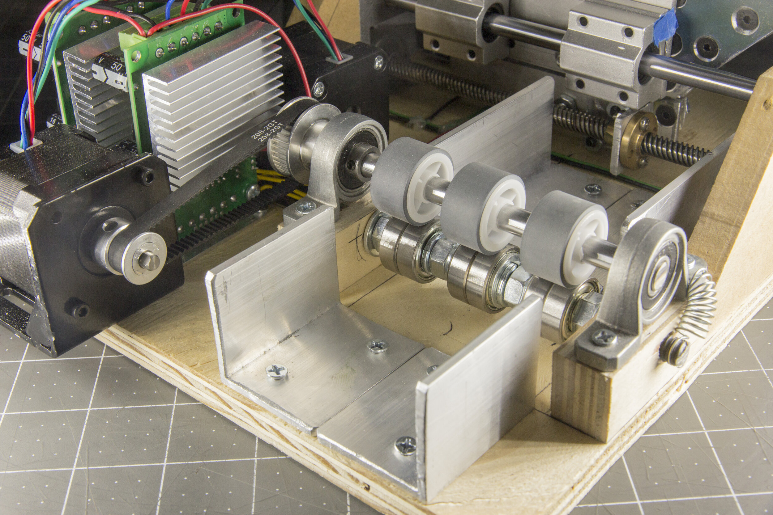
2GT 5/8mm bore pulley + belt kit (for carriage and paper puller)
More 2GT 5mm bore pulleys (for punch)
128mm 2GT pulley (for punch)
Another 8mm lead screw + nut (for punch)
There are also some parts that have to be improvised. For the rubber wheels on the paper puller, I used wheels from a printer that I bored out until they fit snugly on the 8mm shaft (the lead screw kit came with two 8mm shafts- I used one to support the carriage, and I used a bit more than half of the other for the paper puller shaft, and the rest for the punch). The bracket that holds the gear motor on the punch also came out of the same printer that the rubber wheels came from.
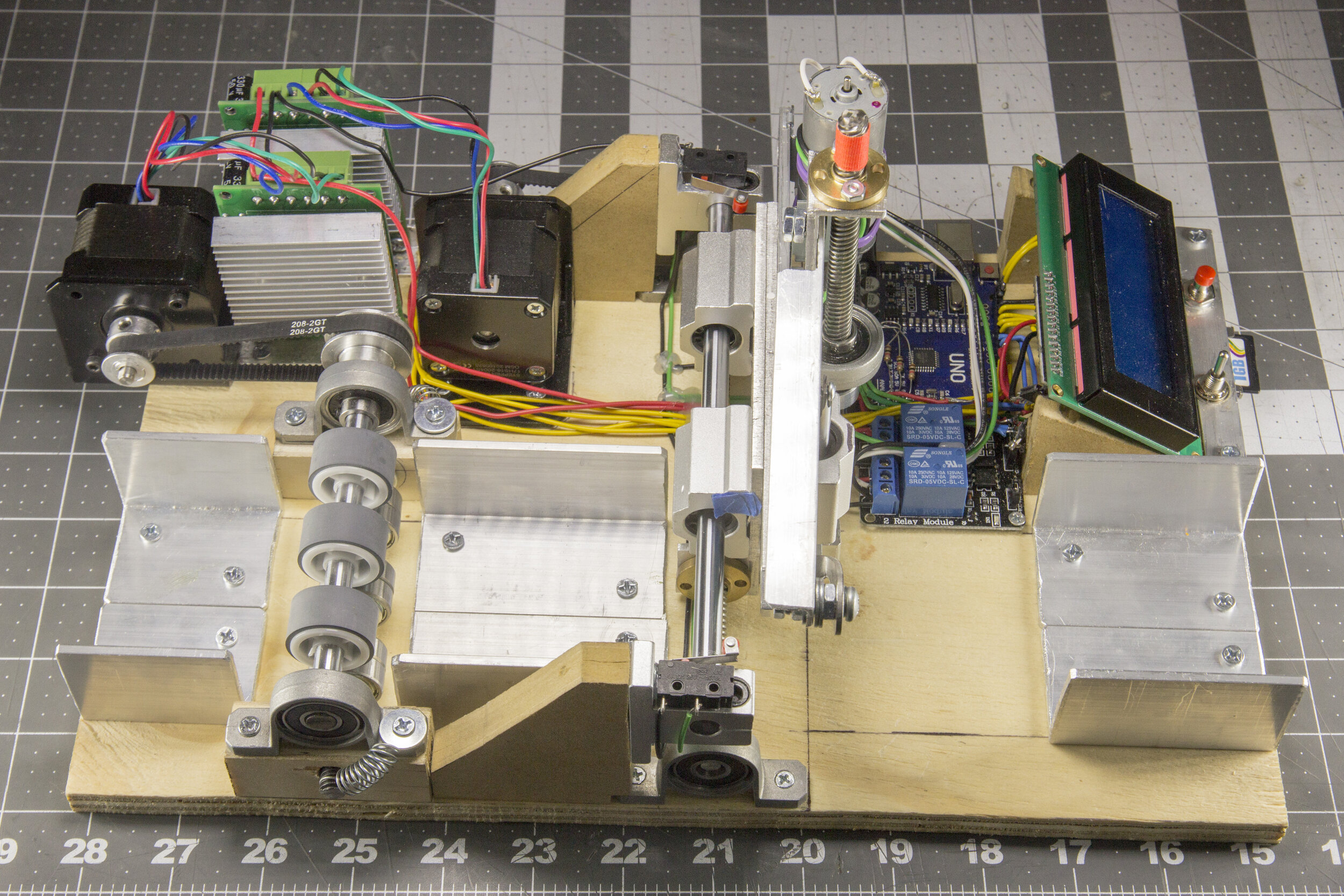
The carriage is the assembly that slides horizontally and carries the punch. In order to be able to bolt the linear bearings on the back of the carriage and the hole punch components on the front, I made the hole punch and the carriage base two separate plates that bolt together. If it were a single plate, it would be impossible to use bolts to attach the components because of the components in the way on the other side. I used countersunk screws to so that the two plates can connect flushly together. This ended up being a nice design because it was convenient to be able to separate the punch assembly from the rest of the machine when I wanted to work on it.
How to make a Hole Punch
Making a hole punch turned out to be extremely challenging. There are three parts to a punch: the punch, which penetrates the paper, the die, which is the hole that is punched into, and the stripper, which in my case is just a little foot that keeps the paper held down as the punch retracts. Making a punch is challenging because the punch and the die have to be very precisely aligned, and the size tolerances of the die hole with respect to the punch diameter must be very tight. I also had trouble getting an actuator with enough force to drive the punch through the music box paper, which is thicker than most paper.
The initial design (right) used two solenoids on either side of the punch, pulling it down into the paper. I figured out early that this might not be strong enough, so I switched to using a class 2 lever with the two solenoids at the end of the lever.
This was still not enough force, so I switched to using a single larger solenoid. This also didn't work, so I resorted to using a motor and lead screw, which provided more than enough force. I didn't want to have to do this because I thought it would be much slower than a swift blow from a solenoid, but it ended up not being as bad as I thought.
Most of my trouble and frustration was trying to manufacture the punch and die. I used one of the linear bearings from the lead screw kit to guide the punch, and I originally wanted to use one of the 8mm rods that came in that kit for the punch (the linear bearing and 8mm rod are made for each other so this would be ideal). I hoped to use a lathe to turn down one end to the diameter of the punch, but the rod was hardened and could not be easily worked. So instead I took larger steel stock and tried to turn it down to 8mm, then also turn down the punch end to about 3mm. I made three attempts to do this and they all failed in different ways.
Matt had an idea to use the original punch head that came with the music box, which would be nice because that would mean I would not have to turn down to that tiny radius on the lathe. I also found out that I could use the hardened 8mm rods I originally wanted to use if I grind past the hardened layers of material. I found that I was able to bore a hole in end of the stock to fit the punch head, and I was able to drill the holes in the top if I ground it down a little bit first. Because I'm using this stock, I wouldn't have to turn larger steel stock down to 8mm, which was very hard when I tried it before. So now I don't have to turn any precise diameters on a lathe, which was nice. This solution worked out very well for the punch head.
The die is a simple block of aluminum that I milled down to shape, but this could also be made with hand tools. I made the mounting holes significantly oversized to allow the position of the die to be adjusted until it aligned will with the punch. I also made it a little short, so I could shim it with paper between the die and the carriage until it aligned correctly.
These are the three main iterations of the hole punch assembly:
Conversion Tool + Source Code
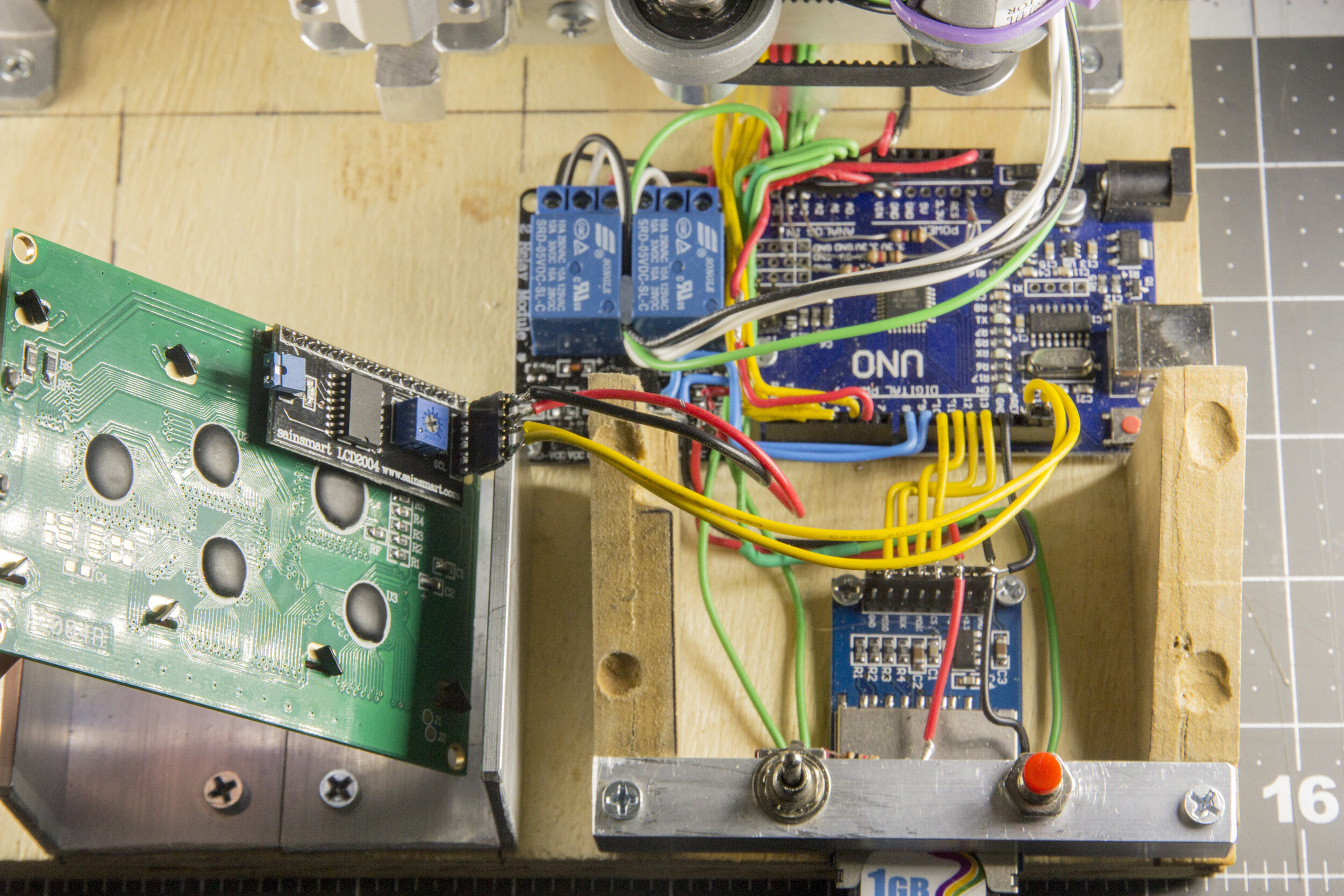
Standalone .exe applications for the conversion tool, along with the Processing source and Arduino source code, are found in this Drive folder. Using Processing or running the executables requires Java 8 or higher. The executables have to run in the context of their folders in order to be able to access the libraries they need to run. If you have stability issues running the executables, you can try downloading Processing, opening the source code, and running it from within Processing.