Stepper Organ
I've spent the last two months building this very strange instrument. The idea came a few months ago, when I was thinking about how stepper motors work and the idea occurred to me that steppers would probably generate alternating current when backdriven. I got an oscilloscope and I found that this was true, which was exciting because that meant that I could use stepper motors to generate sound. This is because AC is a wave, which is what sound is. If you amplify the signal and send it to a speaker, you can listen to it as sound. The frequency of the signal from the motor is proportional to how fast the motor is driven. So if you backdrive the motor at a high speed, you get a high pitch, and a low speed would give you a low pitch. The wave I got from my stepper motors was more or less sinusoidal, which meant I'd get sound similar to what you get from a sine synthesizer.
I had also seen Wintergatan's then recently released marble machine video. The machine is magnificent. I watched all of the prologue videos documenting the process of building the machine, and I was inspired. This and the stepper motor ideas were all floating around in my head at the same time, and eventually the ideas collided. I decided to build a musical instrument.
Design
My initial concept was to have one motor for each note, and each motor would have a spool wrapped with thread. On the end of the thread is a weight. When the note is played, the weight is released and would pull down on the spool, spinning it, and thus spinning the motor. The higher notes would have bigger weights so they would spin the motors faster and generate a higher pitch, and the low notes would have smaller weights.
There were a lot of problems with this idea. Gravity accelerates mass towards the earth. It does not pull things at a constant speed, which is what I would have needed to make a constant pitch. I was hoping that I would be able to make a system with an internal friction resistance such that the terminal velocity of my weights would be reached quickly enough to get to the desired note quickly and such that each note would be easily tunable to get the range of notes I would need. After playing around and thinking about it for a while, I decided that this kind of system just didn't seem achievable.
The other issues with my design were that I would need some sort of rewind to pull the weights back up when they weren't being played, so I wouldn't eventually run out of string. Or alternately, just make the instrument very tall so that the notes do not need to be rewound. Either way, I think it would have been very messy.
So I fell back on my plan B: a series of spinning disks that each stepper motor can engage with, where each disk is sized so that they move at a different speed on the outside edge such that they backdrive the stepper motors at the correct speeds to generate pitches that are in tune with each other.
I decided to do four octaves, which is 49 notes. 49 keys, 49 stepper motors, disks, lever arms. 49 of a lot of things to do, as I would soon find out.
Construction
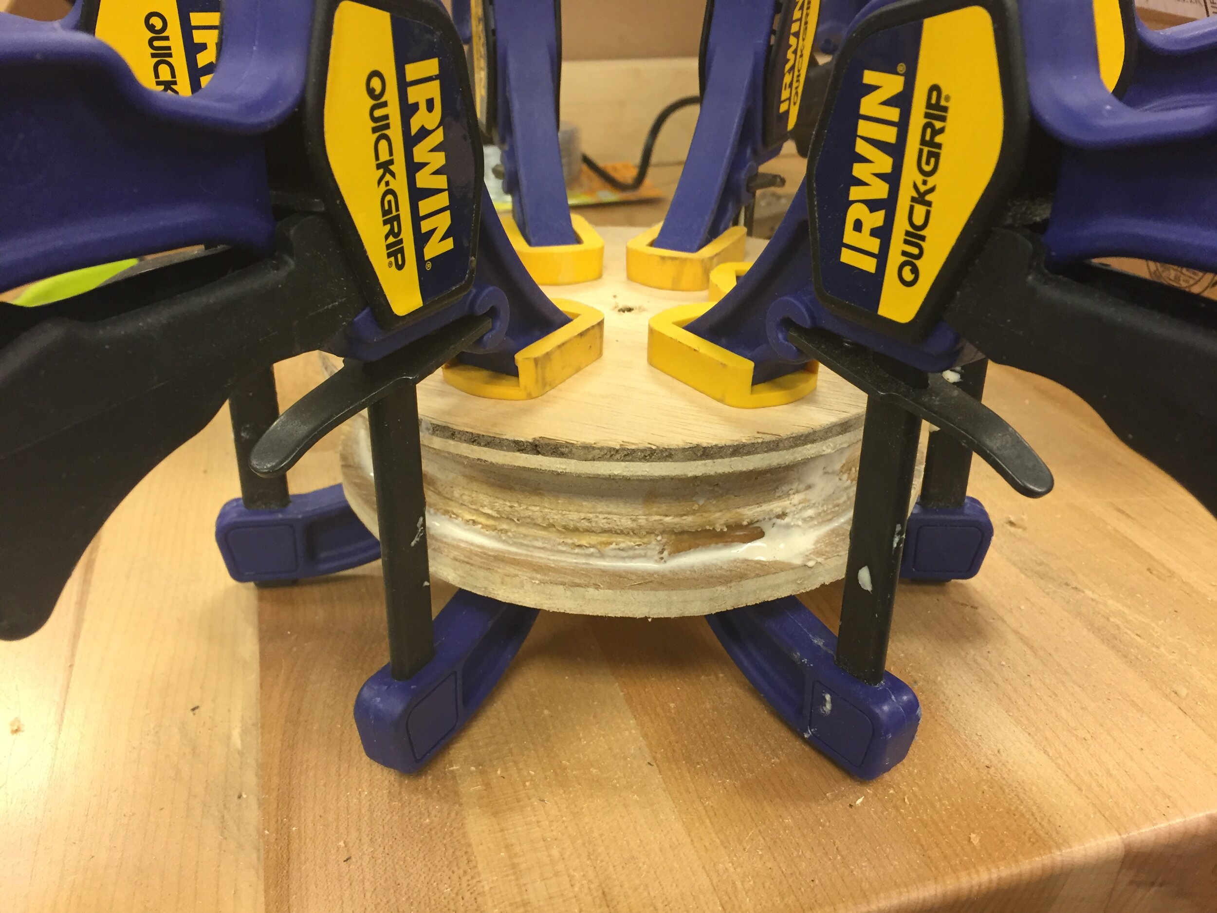
My first challenge was to make the disk stack. This is the most important and central piece of the instrument, so I did this first. I knew if I did this, I would have to do the rest of it because I'd have no other excuse to own this massive stack of 49 circles.
I considered cutting the shape out of a solid block by hand or on a giant lathe if I could find one, but no lathe I could ever hope to get access to would have been big enough. Instead, I decided to make each disk a separate piece. This ensures that the width of each section of the cone is constant, and it also allows me to replace an individual disk from the stack if it gets damaged instead of having to remake the entire thing.
I sent some emails around the engineering department on campus, pitching my project, and eventually was allowed to use a CNC to cut the disks and later also a machine shop for other parts of the project, although it felt a little reluctant. I think people are protective of their tools, and are skeptical of independent student projects that aren't affiliated with engineering classes.
The CNC was very important, because it would be able to cut perfect circles that are the perfect sizes, and do 49 of them quickly. It's crucial that the disks are correctly sized relative to each other, or the instrument would be out of tune. I used this note frequency chart to determine the correct size ratios of the disks, and I made this spreadsheet using those values to calculate the final sizes. From there, I laid out the circles on 4x4' sheets in Inventor, and those drawings were used to cut the MDF on the CNC.
The final assembled disk stack weighs about 90 pounds. Quite hefty. Fun fact: if I did 88 notes instead of only 49 and I started at the same size for the lowest note, the highest note disk would be 16 feet in diameter.
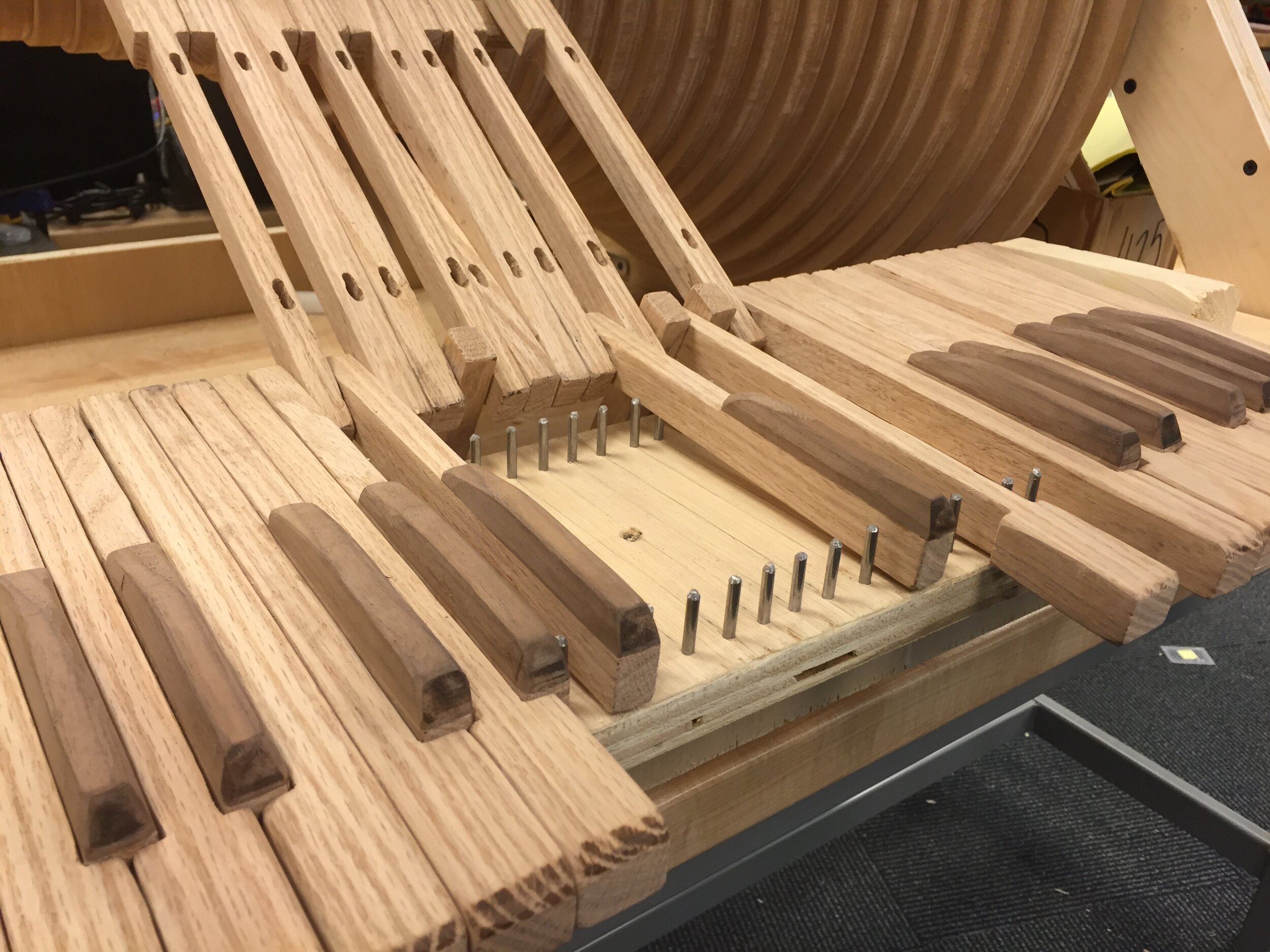
The keys are made of oak, with walnut key tops for the darker colored accidentals. I eventually applied two coats of finishing oil to the keys because I thought they would most likely get dirty and stained over time, so the oil might help to protect them.
Next, I built the frame to hold up the disk stack, the keyboard, and the point where the lever arms would be in the future. Up to this point, I wasn't sure what this was going to look like. The design I came up with is simple and sturdy. I thought it would need more diagonal reinforcement, but it turned out to actually be quite rigid.
With the keys done and the disk stack mounted in the frame, I could start to visualize what it was going to look like. This is where things started to get really hard. The monotony of doing so many things 49 or 98 times was intense and persisted for the rest of the build.
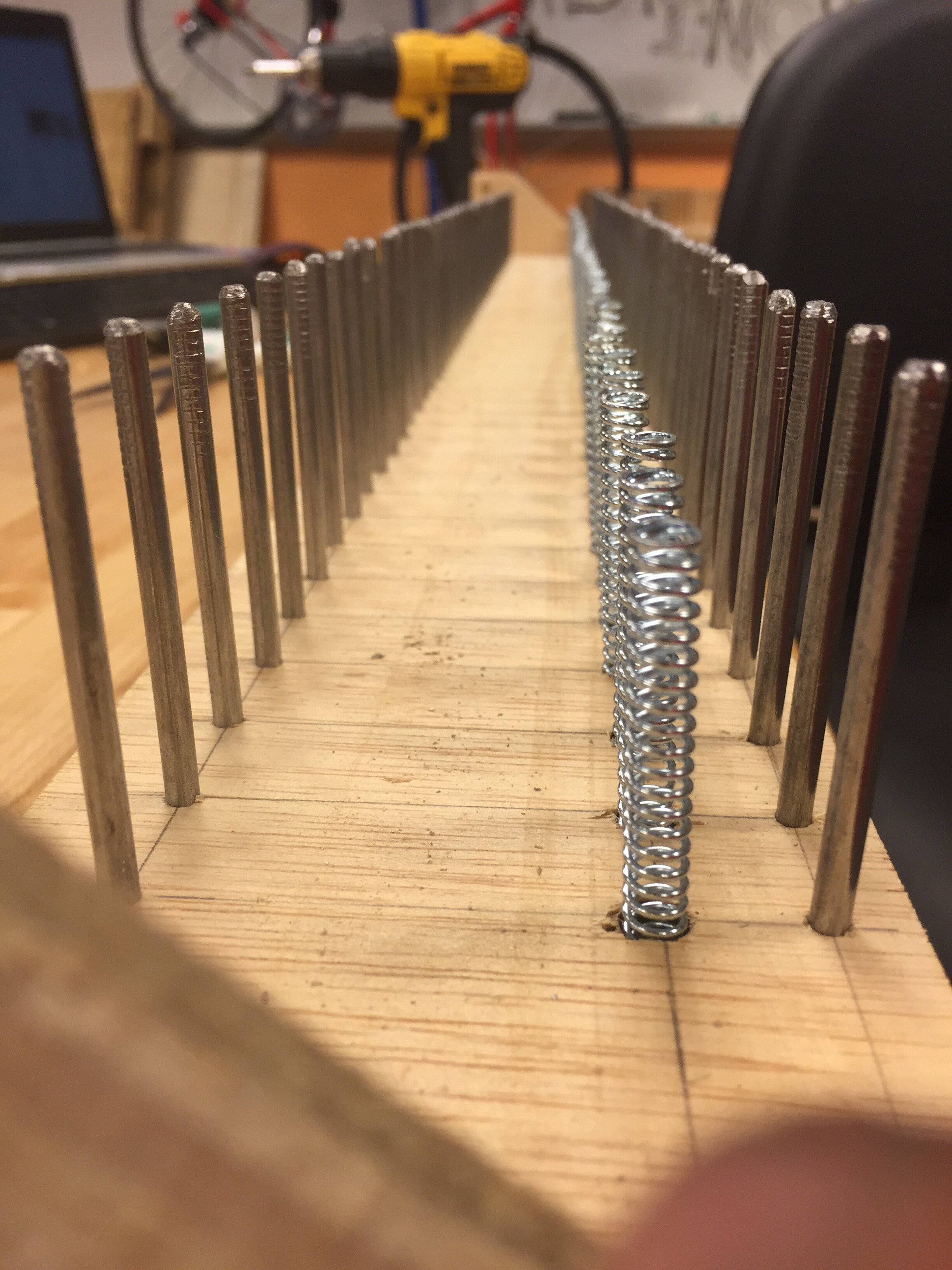
For the keys, these tasks included the 98 pegs arranged on the key board to keep the keys aligned, and the corresponding 98 channels cut in the bottom of the keys.
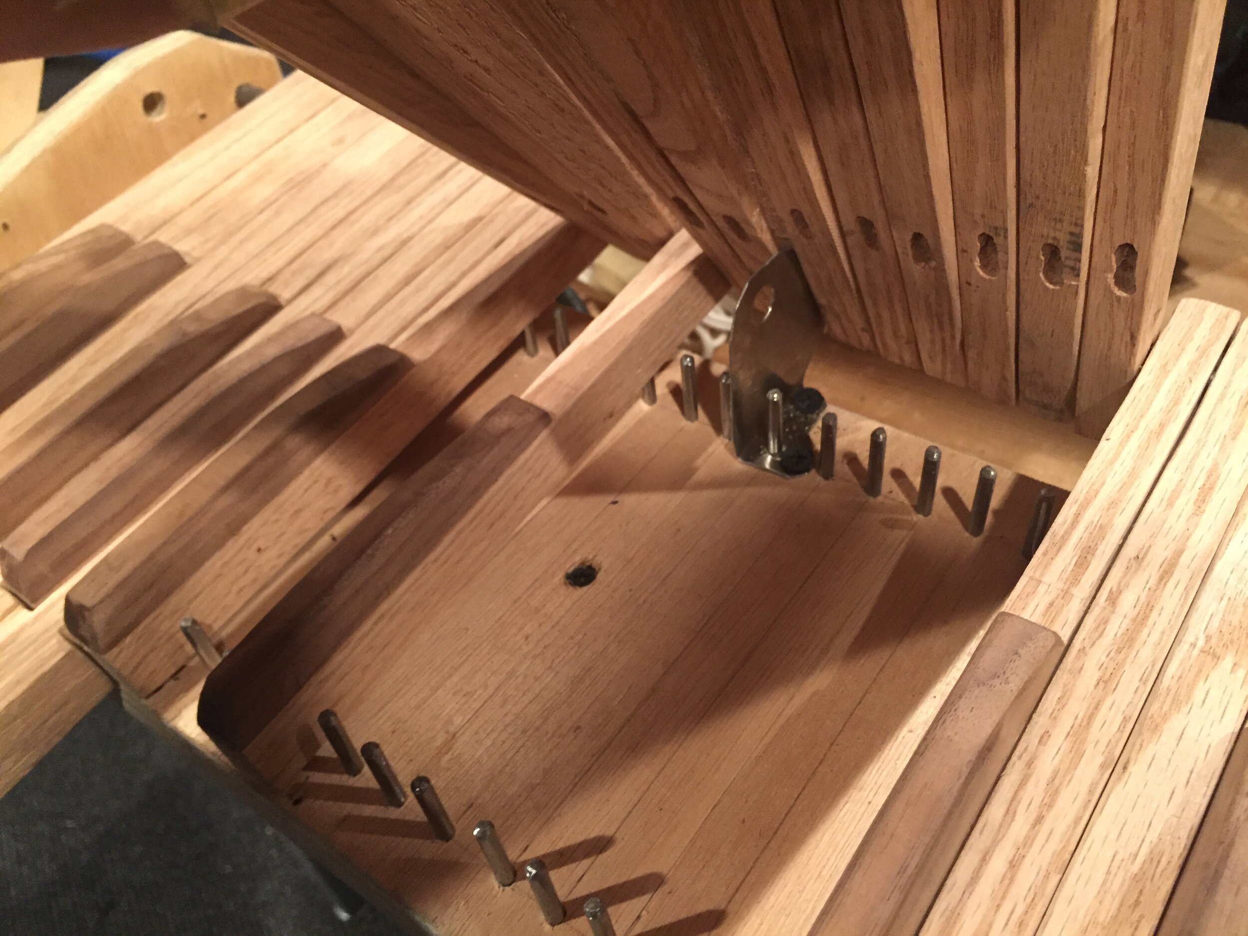
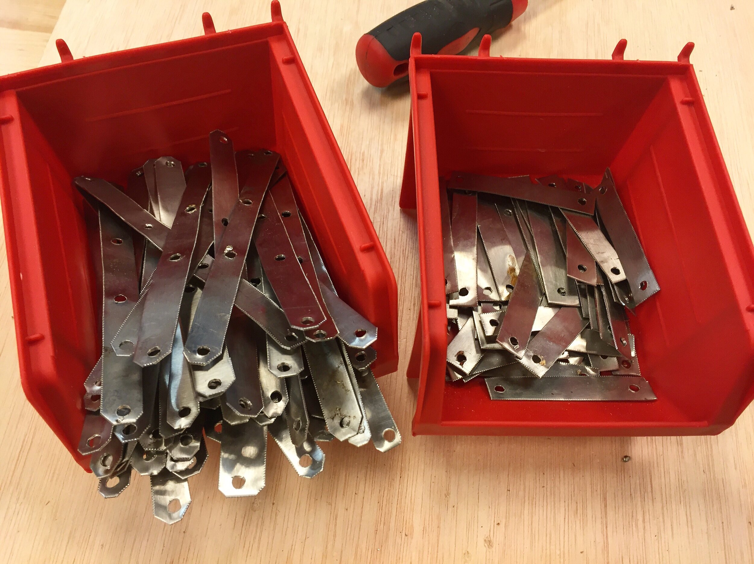
For the levers, I cut 48 lever bases and 48 unique lever arms, all at different angles and lengths. The high C is just a straight piece, so the base and arm are combined into one piece for this note. Each lever pivots on a steel rod with a bearing cut out of a steel tube, ground flat against the wood. These also are held in position by 98 pegs, and are supported by 49 springs. The lever bases and lever arms are connected by 96 brackets cut from sheet metal: one long bracket fastened with four screws on the top of each lever and one short bracket fastened with two screws on the bottom of each lever.
The angle and lengths of each unique lever arm was calculated in this spreadsheet, the same one from the disk stack. To make them the correct sizes, I used a ceiling mounted downward facing projector to project my layout, and traced each arm onto the plywood. This is not as precise as laser cutting or printing a template, but it was sufficient. I would be able to make slight adjustments to the lengths of each arm when mounting the upper lever arms to the lower lever arms.
For electronics, the high notes, which are the stepper motors that are being backdriven faster, not only generate a wave that is higher in frequency than the low notes, but it is also higher in amplitude. This means the high notes would be much louder than the lower notes, so each note has its own volume knob so the higher notes can be trimmed down. I used logarithmic potentiometers, and I read this article and used the circuit from figure 4, minus the recovery amplifier. I think there was a problem with using so many input channels, so I just took the output directly from the mix point shown in that diagram and that seemed to work fine.


Installing the keys and attaching the arms were the most labor intensive processes. Everything had to fit together well and move freely in very tight proximity to other moving parts. When something isn't moving smoothly, it's never really clear if it's rubbing against an adjacent key or lever, or if it's rubbing against one of the pegs, or if something else is catching. It's a long process of sanding and grinding at things until it starts to move.
Getting the unique lower lever arms all installed correctly was also very time consuming. They all had to be straight and aligned so the motors properly engage with the disks and so they don't rub against adjacent levers in any of many possible ways.
To make the instrument easier to move, the disk stack can be disengaged from the motor and lifted off its bearing mounts to be removed. However, in order to roll it out from underneath the levers, this back piece (above) would need to be removed, so I replaced the screws that attached it with bolts. I made this change after filming the video.
Results and Persisting Problems
Features Never Implemented
There are two features I wanted to add that I was not able to add during the two months I spent on this project.
The first is adding a tachometer that shows how fast the disk stack is spinning. I got this really cool vintage tachometer and flexible shaft from eBay.
This is why there is an unused pulley on the large side of the disk stack. This was meant to link to another pulley on the end of the flexible shaft, and the other end of the flexible shaft would couple with the tachometer. This way, you could monitor how fast the disk stack is spinning, which is an indication of which key the instrument is playing in. There would be markings on the tachometer showing the speeds of different keys. This would allow you to accurately reach a desired key, and also allow you to change speeds to do gradual key changes on the fly while playing.
I came very close to finishing this, but I had two problems. The first was that I could not affix the pulley end of the flexible shaft securely enough that it could handle the belt tension against the disk stack pulley. The other reason is that the alignment between the other end of the flexible shaft and the tachometer had to be extremely precise, or else it would catch periodically or the tachometer would not spin without excessive resistance.
The other big feature I wanted was the ability to drive the disk stack by pedal power rather than by a motor. This would involve building an entire base for the instrument to sit on instead of resting on a table. Inside of that base would be the pedals and some gearing. The disk stack would be disengaged from the motor, and then engaged with the pedals on the new base. Since the disk stack is so heavy, it acts like a flywheel, so I think it would be possible to spin the stack at a pretty constant speed under human power, with the help of the tachometer to monitor the speed.
I didn't build this because I haven't yet had time to and I also have not decided if the quality of the sound of the instrument merits the work of this addition.
Media Links
http://www.popularmechanics.com/culture/music/a22361/stepper-motor-organ/
http://digg.com/video/stepper-motor-organ
http://hackaday.com/2016/08/20/an-organ-made-from-back-driven-steppers/
https://blog.hackster.io/this-diy-organ-uses-49-stepper-motors-to-make-music-35b0de360a43#.384hw9s7b
http://newatlas.com/josh-sheldon-stepper-organ/45016/
http://blog.muzhack.com/an-organ-made-of-stepper-motors/
https://muzhack.com/u/joshs/stepper-organ
https://www.facebook.com/NewYorkMag/videos/10154589839964826/